How to Draw Ellipse in Autocad 2017
Ellipse in AutoCAD
The Ellipse is defined as a curve surrounding two focal points.
The shape of the ellipse is determined by two of its axis, which defines the length and width.
The Ellipse is a general command to create ellipse on the AutoCAD display. We can create the ellipse by specifying the two-point on an axis and the endpoint on another axis.
The first axis and the second axis of the Ellipse can be determined either as minor or major axis, depending on the specification.
The icon of Ellipse will look like the below image:

Move the pointer of your mouse on the Ellipse icon to view the dialogue box for Ellipse in AutoCAD. It will look like the given image:
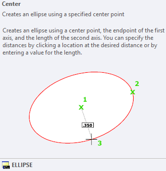
It consists of the drop-down list, which includes other options such as Elliptical Arc, Center, and Axis. The list will look like the given image:
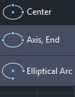
Let's discuss each type of Ellipse in detail.
Center
In this method, the first axis is determined by the center point and endpoint, while the second axis is determined by the length. We can either determine the point or distance value to create such ellipse.
Let's understand with an example.
The steps are listed below:
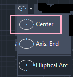
- Click on the Ellipse icon on the ribbon panel and choose Center from the drop-down list of the Ellipse, as shown in the below image:
Or
Type el or ellipse on the command line or command prompt and press Enter.
Type C or copy on the command line.
Press Enter. - Specify the center of the Ellipse on the viewport.
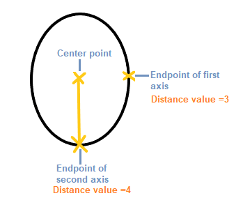
- Specify endpoint of the first axis, as shown in the below image:

We can either specify the point or the distance value. The distance will be calculated from the center to the endpoint of the first axis, such as 3.
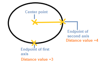
We can also choose the vertical axis as the first axis, as shown in the below image:
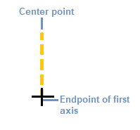
- Press Enter.
- Specify the endpoint or distance value of the second axis. For example, 4.
- Press Enter.
- The Ellipse will be created, as shown in the below image:
If the vertical axis was chosen as the first axis, the ellipse so formed is shown in the below image:
Axis, End
The Ellipse is formed by defining the three points similar to above.
It is shown below:
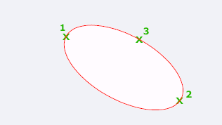
The location and length of the first axis is specified by the points 1 and 2, while the distance between the center and the endpoint of the second axis is specified by the point 3.
Elliptical Arc
The Elliptical Arc command is used to create an elliptical arc.
For example:
Consider the below image:
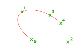
The location and length of the first axis is specified by the points 1 and 2, while the distance between the center and the endpoint of the second axis is specified by the point 3.
The fourth and fifth specified points are the start and end angles.
Let's understand with an example:
The steps are listed below:
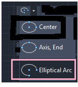
- Click on the Ellipse icon on the ribbon panel and choose Elliptical Arc from the drop-down list of the Ellipse, as shown in the below image:
Or
Type el or ellipse on the command line or command prompt and press Enter.
Type A or arc on the command line or command prompt and press Enter. - Specify the endpoint or the center of the elliptical arc.
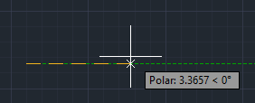
- Specify endpoint of the axis, as shown below:
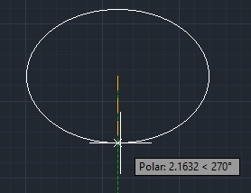
- Specify endpoint of other axis, as shown below:
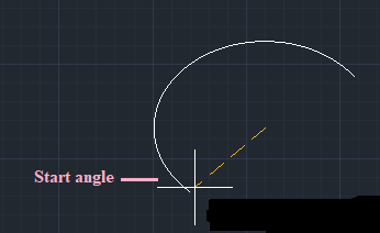
- Specify the start angle. For example, 30. It is shown in the below image:
- Specify the end angle. For example, 120.
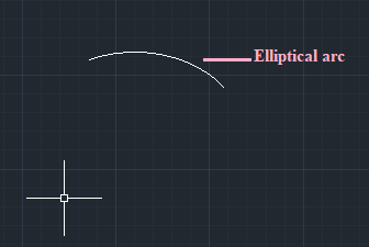
- The created elliptical arc is shown in the below image:
We can also specify the Parameter angle instead of the normal angle.
Parameter
It creates the arc using the following vector equation for the specified angle values:
p(angle) = c + a * cos(angle) + b* sin(angle)
Where,
a and b = negative lengths of the major and minor axis
c = center of the ellipse
Source: https://www.javatpoint.com/ellipse-in-autocad
0 Response to "How to Draw Ellipse in Autocad 2017"
Post a Comment